
@gramex/network
v2.1.2
Published
A force-directed network or graph visualization.

Readme
@gramex/network
A force-directed network or graph visualization.
See the workshop for a step-by-step tutorial.
Example
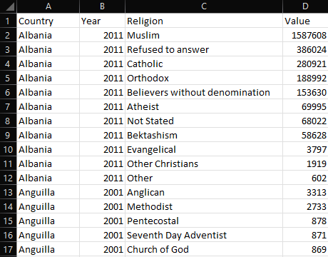
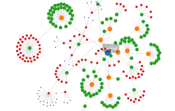
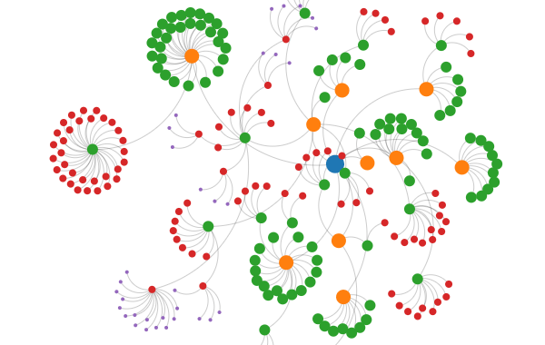
Given this table of countries and religions:
... we can render the following network:
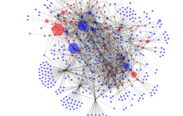
Here is the source code for the network above
Installation
Install via npm:
npm install @gramex/network@2Use locally as an ES module:
<script type="module">
  import { network } from "./node_modules/@gramex/network/dist/network.js";
</script>
Use locally as a script:
<script src="./node_modules/@gramex/network/dist/network.min.js"></script>
<script>
  gramex.network(...)
</script>
Use via CDN as an ES Module:
<script type="module">
  import { network } from "https://cdn.jsdelivr.net/npm/@gramex/network@2";
</script>
Use via CDN as a script:
<script src="https://cdn.jsdelivr.net/npm/@gramex/network@2/dist/network.min.js"></script>
<script>
  gramex.network(...)
</script>
Use a node-link dataset
The network() function accepts a { nodes, links } object.
nodesis an array of objects.linksis an array of{ source, target }objects that to the node by index number or by reference.
{
  "nodes": [{ "name": "Alice" }, { "name": "Bob" }, { "name": "Carol" }],
  "links": [
    { "source": 0, "target": 1 },
    { "source": 1, "target": 2 }
  ]
}
If nodes has an id key, you can specify the links using id:
{
  "nodes": [{ "id": "Alice" }, { "id": "Bob" }, { "id": "Carol" }],
  "links": [
    { "source": "Alice", "target": "Bob" },
    { "source": "Bob", "target": "Carol" }
  ]
}
Here is a simple network that draws the above dataset:
const graph = network("#network", data);
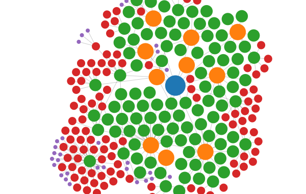
Style nodes and links
Update the attributes and styles of the returned .nodes and .links joins to style the nodes and links.
By default, the nodes are rendered as <circle> elements and links as <line> elements.
You can apply the D3 .attr,
.classed,
.style,
.text,
and any other selection methods to style the elements.
You can use any node/link keys in the styles. For example:
const graph = network("#network", data);
graph.nodes.attr("r", (d) => d.depth);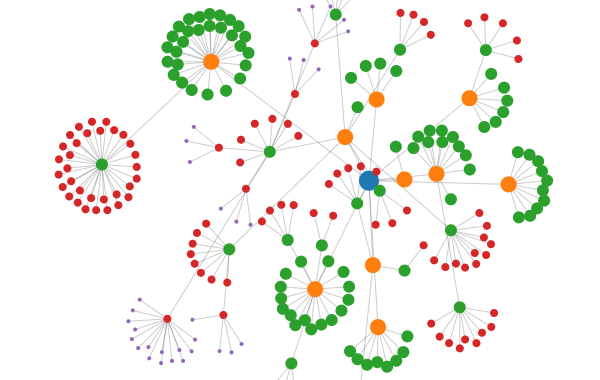
See how to style nodes and links
Add tooltips
You can use Bootstrap tooltips.
- Add a
data-bs-toggle="tooltip" title="..."attribute to each feature usingupdate - Call
new bootstrap.Tooltip(element, {selector: '[data-bs-toggle="tooltip"]'})to initialize tooltips
Dragging and pinning
Dragging a node pins it where you release it. Double-click a pinned node to unpin. To unpin all nodes, double-click on the background.
When dragging, the node gets a dragging class. When pinned, it gets a pinned class. You can use this to style nodes that are dragged or pinned. For example:
.dragging {
  stroke: black;
  stroke-width: 5;
}
.pinned {
  stroke: black;
  stroke-width: 3;
}
See how to highlight dragged and pinned nodes
Filter nodes and links
To dynamically filter nodes and links, pass a subset of the SAME nodes and links.
Make sure the nodes and links are the same objects as the original nodes and links. This ensures that the simulation is not restarted.
In this example, when you move the slider, the country - religion links are filtered based on population. Any isolated nodes are also removed.
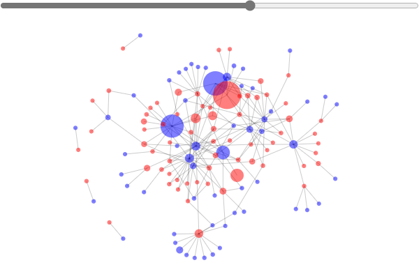
See how to filter nodes and links
Tabular data
Any tabular data can be converted into a node-link structure. For example, take this table of countries and religions:
Convert this into a flat array of objects like this:
const data = [
  { Country: "USA", Religion: "Christian", Population: 100 },
  { Country: "UK", Religion: "Christian", Population: 90 },
  { Country: "Iran", Religion: "Muslim", Population: 80 },
];
Now you can convert it to a node-link dataset using { nodes, links } = kpartite(data, keys, values). It accepts 3 parameters:
data- array of objects containing the data.keys- object of{key: column}pairs or an array of[key, column]pairs.keyis a string node typecolumnis the string name of a field in data, or a function(object) that returns the field, or a static value.
values- object of accessor functions for link values that are aggregated across links and nodes
For example:
const { nodes, links } = kpartite(
  data,
  {
    Country: "Country", // Create a node for each country
    Religion: (d) => d.Religion, // Create a node for each religion
  },
  {
    count: 1, // Count the number of links between countries and religions
    Population: "Population", // Sum the population of countries and religions
  },
);
This creates the following nodes:
[
  {
    key: "Country",
    value: "USA",
    id: '["Country","USA"]',
    count: 1,
    Population: 100,
  },
  {
    key: "Religion",
    value: "Christian",
    id: '["Religion","Christian"]',
    count: 2,
    Population: 190,
  },
  // ... etc.
];
... and the following links:
[
  {
    source: {}, // link to USA source node
    target: {}, // link to Christian target node
    id: '["[\\"Country\\",\\"USA\\"]","[\\"Religion\\",\\"Christian\\"]"]',
    count: 1,
    Population: 100,
  },
  // ... etc.
];
Tabular unipartite data
If you have a relationships between the same entity (e.g. people connected with people, countries trading with countries),
use kpartite() as follows:
// Create nodes and links, mapping the "name" key with both "Column A" and "Column B"
const { nodes, links } = kpartite(
  data,
  [
    ["name", "Column A"],
    ["name", "Column B"],
  ],
  { count: 1 },
);
Here is an example with the Friends sexual partners
data.
(Interestingly, Rachel is the only one who doesn't share a sexual partner with any of the others.)

See how to generate unipartite data
Here is an example with the Arxiv paper coauthors
data of Computational Lingustics papers that have "LLM" in their title, and authored 2+ papers together.
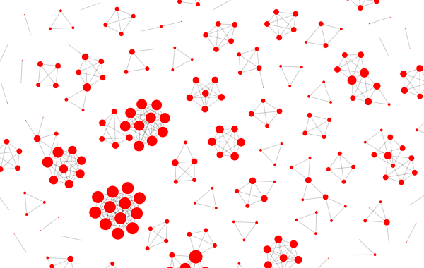
See how to generate unipartite data
Forces
By default, the network uses the following forces:
link: ad3.forceLink(links)that links the nodes and linkscharge: ad3.forceManyBody()that pushes nodes apartx: ad3.forceX(width / 2)that centers the nodes horizontallyy: ad3.forceY(height / 2)that centers the nodes vertically
To disable these or modify the forces, pass a force object with the required forces. For example,
this network uses a d3.forceCenter() force instead of x and y:
forces: {
  x: false,
  y: false,
  center: ({ width, height }) => d3.forceCenter(width / 2, height / 2),
}
This network uses a d3.forceCollide() to prevent nodes from overlapping, and a stronger
d3.forceManyBody() replacing the default charge force to push nodes apart:
forces: {
  charge: () => d3.forceManyBody().strength(-20),
  collide: () => d3.forceCollide().radius(d => 22 - d.depth * 4).iterations(3),
},
Each force is a function({ nodes, links, width, height }) where width and height are the size of the SVG. It should return a D3 force.
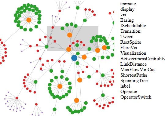
Brushing
Passing a brush function enables brushing. The brush function is called with the selected nodes as parameters. You can use this to update other visualizations.
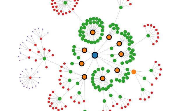
Node shapes and labels
By default, nodes are <circle> elements. Change nodeTag for a different shape. For example, to use <text> elements:
const graph = network("#network", { nodes, links, nodeTag: "text" });
graph.nodes.text((d) => d.id);
Here is a detailed example on how to draw labels with text and a rectangle background:
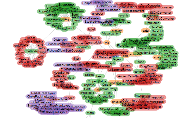
See how to use different node shapes
Arrows
To add arrows, add a triangle <marker> to your SVG's <defs> like below:
<svg>
  <defs>
    <marker
      id="triangle"
      viewBox="0 0 10 10"
      refX="20"
      refY="5"
      markerUnits="strokeWidth"
      markerWidth="8"
      markerHeight="8"
      orient="auto"
    >
      <path d="M 0 0 L 10 5 L 0 10 z" fill="rgba(0,0,0,0.2)" />
    </marker>
  </defs>
</svg>
Here:
refXis the distance from the end of the line to the tip of the arrowrefYis the distance from the center of the line to the center of the arrowmarkerWidthandmarkerHeightare the size of the arroworientis the direction of the arrow.automeans the arrow points in the direction of the line
Then add graph.links.attr("marker-end", "url(#triangle)") to your code.
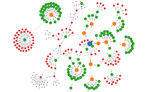
See how to draw arrows on links
Curved links
To draw curved links, set linkCurvature to a number between -1 and 1. 0 is a straight line. 1 is a half-circle. -1 is a half-circle in the opposite direction.
Stop and restart simulation
To stop or restart the simulation, call graph.simulation.stop() or graph.simulation.alphaTarget(0.3).restart().

Bring your own D3
If you already have D3 loaded, or want to use a specific version / instance of D3, pass it to network(el, { d3 }):
See how to use your own D3 version
React usage
Use the following pattern when using `network()`` with React:
const { useEffect } = React;
function App() {
  useEffect(() => network("#network", { ... }), []);
  return React.createElement("svg", { id: "network", width: 600, height: 380 });
}
const root = ReactDOM.createRoot(document.querySelector("#root"));
root.render(React.createElement(React.StrictMode, null, React.createElement(App)));
See how to use network with React
Here are instructions to create a React Component:
npx create-react-app network-react
cd network-react
npm install d3 @gramex/network
Create src/NetworkComponent.js with this code:
Modify src/App.js as follows:
Then run npm start or npm run build.
API
Release notes
- 2.1.0: 31 May 2024. Support stop and restart
- 2.0.0: 24 Nov 2023. Synchronous API. Bring your own D3. To migrate from v1:
- Replace
await network(...)withnetwork(...) - Pass
d3as a param, e.g.network(el, { d3 })
- Replace
- 1.0.8: 14 Sep 2023. Stop past simulations on re-run. Use MIT license
- 1.0.7: 7 Sep 2023. Support any node shape.
- 1.0.6: 6 Sep 2023. Enable styles on pinned nodes
- 1.0.5: 6 Sep 2023. Initial release
Authors
- Anand S [email protected]
- Aayush Thakur [email protected]
- Chandana Sagar [email protected]